
Razak School space frame design for EIMARACE 2012 Leave a comment
steering parts Leave a comment
FORMULA SAE STEERING SYSTEM Leave a comment
Steering Design for a Formula SAE-A Open Wheel Race Car Leave a comment
Weight Transfer Leave a comment
Quite possibly the most important factor in a car’s reaction to driver input is the position of the weight on the four wheels. The balance of this weight can determine if the car will understeer, oversteer, spin, or perform perfectly.
When a car is at constant velocity, the weight is evenly distributed between the four tires. During acceleration, weight will shift from the front onto the rear tires. During braking, the weight shifts from the rear onto the front wheels. During cornering, the weight shifts from the inside tires to the outside tires. Thus, if you were accelerating while turning right, the least weight would be on the front right tire, and the most weight would be on the rear left tire. Tires with less force on them will lock up faster and lose more traction than those with more force. It is important to note that actual mass does not shift in the car. Instead, the suspension causes the body to tilt, and apply the force differently.
A car with a lower center of gravity will transfer less weight, as will a car with a stiff suspension. A car with a high center of gravity or with a loose suspension will transfer more weight. This is why SUVs are so prone to rolling. Their CG is high, and in a sudden change of acceleration and/or direction, can transfer too much weight.
The value Lf is the force on the front wheels, and Lr is the force on the rear wheels. Lf + Lr always equals the weight of the car. In our 1455-kg car, which weighs about 14260-N (1455*9.8) braking at 1-G will cause about 14260-N of braking force. If we also know the car’s wheelbase (2.54-m) and the height of its center of mass (.51-m) we can find the amount of weight transferred. The equation to find the Lf and Lr is as follows:
Lf = d (weight) – Fh/w
Lr = (1-d)(weight) + Fh/w
In this equation, F is the acceleration force. When accelerating, F would be positive, and when braking F is negative. The value for d is the fraction of weight in the front, when the car is stopped. In our example we assume a 50/50 weight ratio.
As an example, let’s say our car is braking at 1-G. We can easily find the new weight distribution:
Lf = .5(14260) – (-14260)(.51) / (2.54)
Lf = 7130 + 2863
Lf = 9993-N
Lr = .5(14260) + (-14260)(.51) / (2.54)
Lr = 7130 – 2863
Lr = 4267-N
So, in a one G braking maneuver, 2863-N will transfer from the rear to the front. In terms of kilograms, the front now weighs 1020-kg, and the rear weighs 435-kg. One G of braking causes a serious transfer of weight. If the driver attempted to turn, he would have huge oversteer with all that weight on the front tires.
space frame3 Leave a comment
space frame Leave a comment
space frame2 Leave a comment
Leave a comment
Car chassis construction
Chassis have to be stiff enough so that they withstand the forces applied to them. This is point is really important in the suspension settings. If the chassis bends a little the car in not going to behave as expected (as linear) because the ride is being modified, in short, the suspension settings are modified. However, you can not make the chassis completely stiff. That would cause it to be brittle. There will start to appear weak points and it would end breaking throw the weakest. So you need to reach a point where it is neither too stiff nor too weak.
As said before, the car needs to withstand various forces, so which are these forces:
- Lateral G (cornering speed)
- Longitudinal G (determined by acceleration and braking
- Load (passengers or goods)
- Road irregularities (bumps, surfaces and cambers)
The main materials used to build chassis are steel alloys , aluminium alloys, titanium alloys composites… Everyone of those have different properties and applications. Prices vary vastly.
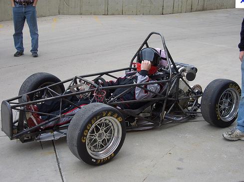
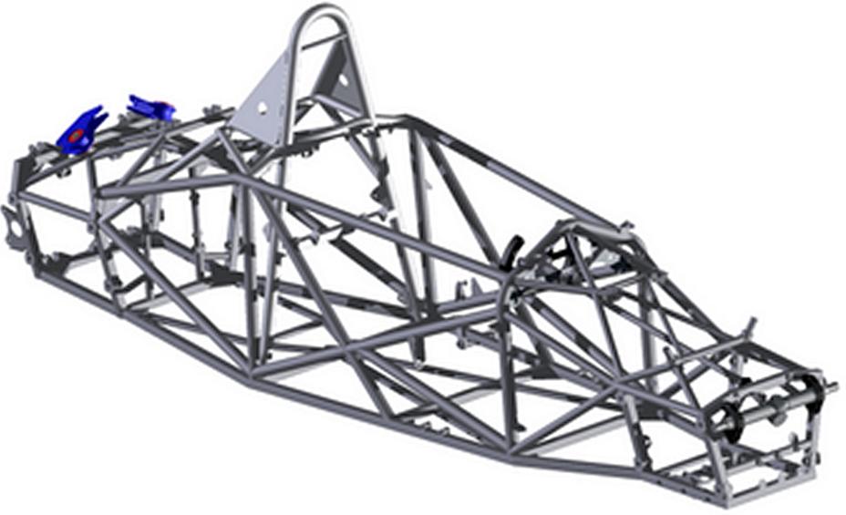
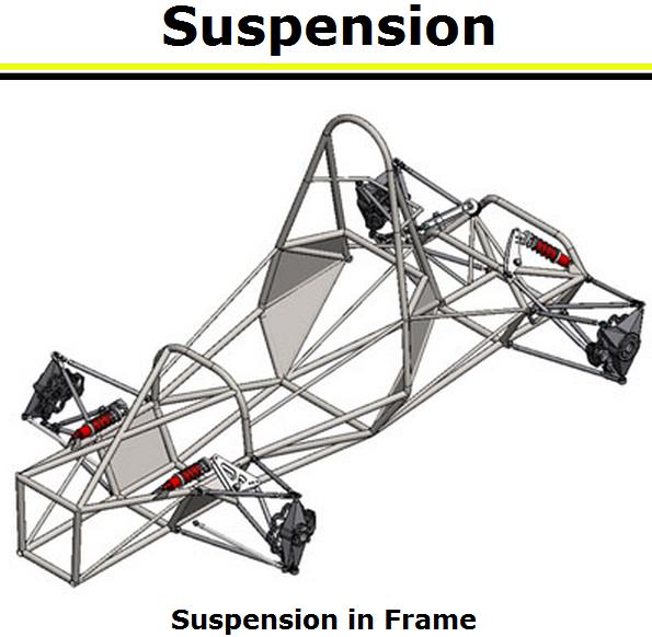
Space frame
Uses several small tubes to create a 3D chassis. Tubes are placed in several directions to cope with the forces they need to withstand. Normally, these chassis are designed for a purpose. These tubes are welded together. To make the welding simpler square-section tubes are also used (however, circular tubes provide the maximum strength). They are normally used in sport applications. Optimizing the design makes hard to put openings (like doors). That is why space frame chassis make acceding to the driving seat difficult (high doors). Take for example the 1950’s Mercedes-Benz 300SL Gullwing.
Advantages: Very accurate. High stiffness. Great torsional rigidity. You can select your materials depending on the purpose.
Disadvantages: Very expensive. Handmade. Tubes need to be cut, shaped, welded manually.
Who uses it: Some competition cars. Some sporty road cars use space frame design in some parts of the chassis.
http://www.keithwakeham.com/Files/ChassisDesign.pdf Leave a comment
http://www.keithwakeham.com/Files/ChassisDesign.pdf
Introduction To Chassis Design
